SVI performs testing, in accordance with NFPA 11: Standard for the Inspection, Testing, and Maintenance of Water-Based Fire Protection Systems.
SVI REFURB’S NFPA 11 FIRE PUMP TESTING SERVICES
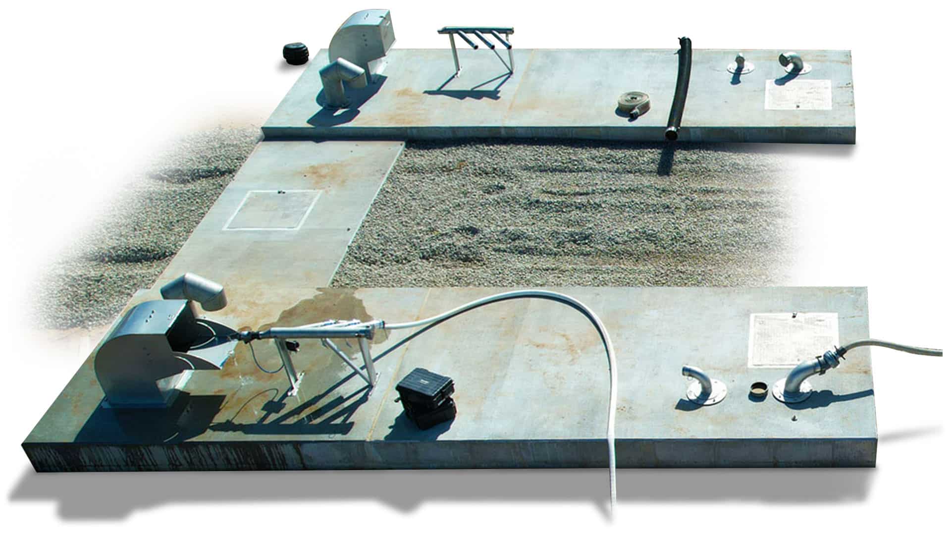
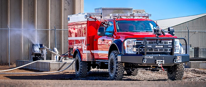
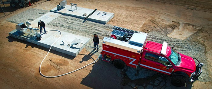
One of the nation’s leading fire engine pump testing companies, SVI Refurb performs NFPA 11 fire pump testing services and certification on-site using our new, state-of-the-art testing facility in Fort Collins, Colorado. SVI Refurb can test the volume, pressure and vacuum of your pump. The testing features a one tank test pit with 20,000 gallons of water. Pressure gauges and water volume pitots are calibrated every six months to ensure accurate test results. Following testing, SVI Refurb will provide a UL Automotive Fire Apparatus Certificate of Inspection for Fire Pump Systems.
THE UL-CERTIFIED TEST INCLUDES:
- Engine speed test
- Pump shift indicator test
- Pump engine control interlock test
- Priming device test
- Vacuum test
- Pumping test
- Overload test
- Pressure control test
- Intake relief valve system test
- Pressure gauge accuracy test
- Flowmeter accuracy test
- Tank-to-pump flow test
OUR TESTING PROCESS:
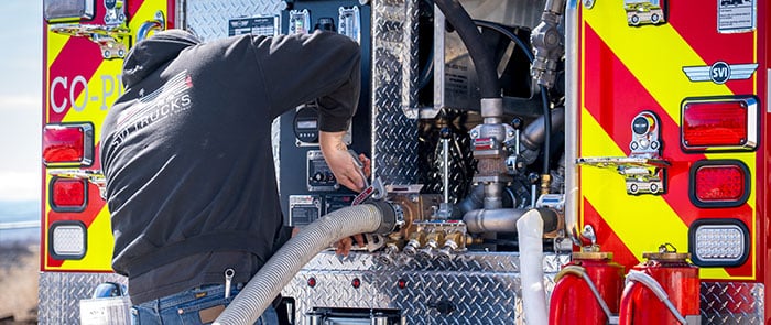
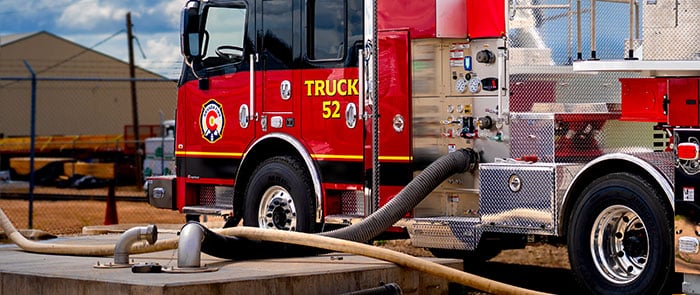
CONNECT HOSES AND TEST METERS
Hoses are connected to the truck per "typical" hose setups. An Ampere meter is connected to measure chassis and body DC voltage loads, and if the apparatus is generator equipped, an AC high-voltage load bank is also connected.
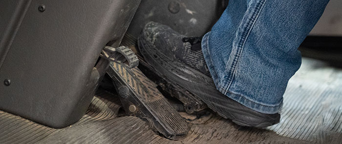
CHASSIS ENGINE SPEED TEST
With the park brake applied, transmission in neutral and pump transmission in "ROAD," the pedal is put to the floor in order to demonstrate the chassis engine's governed RPM.
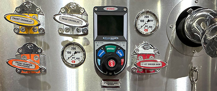
Pump Panel THROTTLE DEMONSTRATION
With the truck in idle, the park brake set, the pump transmission in "ROAD," the truck's transmission is set to anything other than neutral to demonstrate the pump panel throttle is INOP.
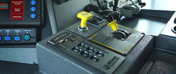
THROTTLE PEDAL DEMONSTRATION
With the pump transmission shifted to "Pump" and the truck's transmission then shifted into "Drive," the engine RPM is increased by 50 RPM and the throttle pedal is locked out.
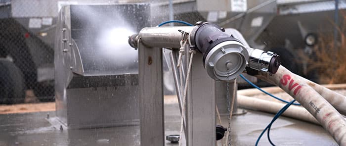
DRAFT DEMONSTrATION
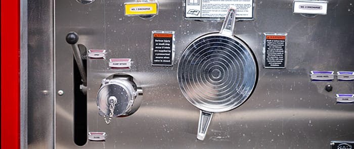
While in "Pump Mode," the PTO generator (if equipped) is engaged. The pump is then primed with the discharge/auxilary intake/drain valves closed, and the main intake valve(s) open. Once water has entered the pump and the pressure increases, a discharge valve that is connected to the pit manifold is opened. The primer switch is then released and the throttle is increased to demonstrate draft is achieved.
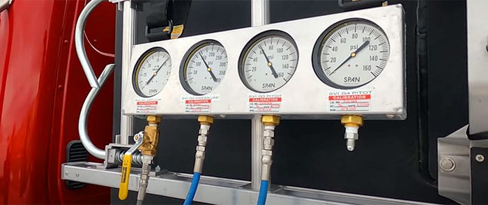
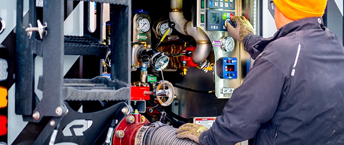
ESTABLISH PITOT PRESSURES
With the net pump pressure set at 150 PSI and the pressure governor in "Pressure Mode," the pitot pressure is established at 100% capacity per a theoretical discharge volumes.
100% CAPACITY @ 150 PSI TEST
If the apparatus is equipped with a generator, an AC voltage load is applied. All DOT, Dome, Warning, Scene, Compartment and Panel lights are turned on, as well as the chassis HVAC. This state is tested for two hours, with gauges monitored every 15 minutes.

OVERLOAD "SPURT" TEST
At the end of the two hours, the net pump pressure is increased to 165 PSI and the pitot pressures are adjusted to their original settings. Testing continues for an additional 10 minutes.
pressure governor test
With the generator load reduced to 50% capacity (if so equipped), and with all discharges closed:
• Pump pressure is tested at 150 PSI = 150 PSI Relief Valve Test
• Pump pressure is at 90 PSI = 90 PSI Relief Valve Test
70% Capacity @ 200 PSI TEST
With the net pump pressure increased to 200 PSI, the pitot pressure(s) are established at 70% capacity per a theoretical discharge volume chart. This state is tested for 30 minutes, monitoring gauges every 15 minutes.
50% Capacity @ 250 PSI TEST
With the net pump pressure increased to 250 PSI, the pitot pressure(s) are established at 50% capacity per a theoretical discharge volume chart. This state is tested for 30 minutes, monitoring gauges every 15 minutes.

TANK TO PUMP AND TANK CAPACITY TEST
With the net pump pressure at 100 PSI, the water tank is filled until overflowing, and intake(s) are closed/capped. The tank is then opened to pump and recirculate tank water. With both tank valves open (and the tank filled at 50% or less), 150 PSI is established on the pressure governor. The tank is then closed as one of the remaining connected discharges is opened; the discharge valve is then opened to establish required tank-to-pump GPM requirements on the pitot gauge. The timer is started and flow is continued until the tank is empty. (Example: A 750-gal. tank, flowing at 500 GPM, test should last 90 seconds.)
DRY PUMP VACUUM TEST
Part 1: With all discharges/intake/drain valves closed, plugs are removed from all gated intakes, a vacuum is pulled onto the pump with the primer until approximately 22 IN/HG is reached.
Part 2: With caps and plugs reinstalled and all gated intakes opened, a vacuum is pulled onto the pump with the primer until 22 IN/HG is reached.
AFTER TESTING, SVI CAN REPAIR AND UPGRADE FAULTY PUMPS:
FIRE PUMP REPAIRS AND UPGRADES
In addition to our pump testing services, SVI Refurb offers a number of pump upgrades. Manual valves can be upgraded to electric-actuated valves to conserve space and simplify operation, followed by panel label updates. We also can upgrade incandescent panel lights to LED for brightness and energy efficiency, and we are the only refurb company in the region to convert high-pressure hoses from 1 inch to large-diameter 4 inches for the ultimate in LDH manifold upgrade to increase water volume over greater distances.